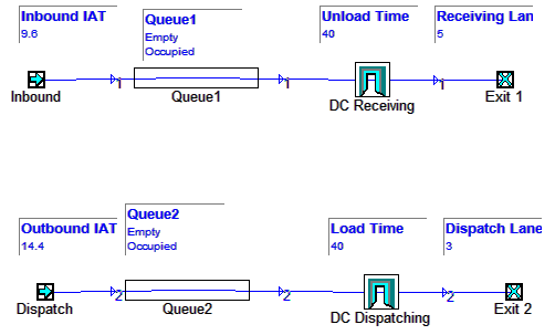
We will now refine our model of a distribution system, by gradually adding details.
We could assert that this initial model we have created shows the complete activity in a distribution centre.
To do so would mean assuming that the entry arrivals represent all types of visitations to the distribution centre, both deliveries and collections. The Load or Unload multiserver could be assumed to be performing either of those functions. Obviously there will be benefit in adding more detail, so we can learn more about the dynamics of the system.
Think about the major elements of a supply chain distribution centre.
Creating the Receival Subsystem
Re-Load DC01 and save it as DC 02.MDL.
Rename your Entry 1 to read “Inbound”.
From the Object Palette, add a Portal to the model and name it “DC Receiving”.
Edit the path so instead of going to the “Load or Unload Server”, it goes through the “DC Receiving” portal instead. Click on one of the arrowheads of the path to select it for Flow editing. Click on the multiserver to put the selection square around it. Now click in it and drag towards the Portal. Let go when the box is flashing around the Portal. It should now replace the multiserver in the path.
Ctrl-O to get to object mode and reposition the objects in a neat row. Copy the Load or Unload Server
About the Portal
A Portal object appears on the screen like any other object but rather than having a fixed behaviour, it is a link to a sub-system screen.
Every Portal contains one Subsystem screen on which there is always at least one Portal Entry and one Portal Exit. A Portal can be classified as “Logical Only”, as it cannot itself hold items. Only the capacity objects in the subsystem can hold items.
No time passes while an item moves into or out of a Portal. An item entering a portal is 'teleported' to the sub-system screen and appears on that screen at the Portal Entry object, and proceeds along its path. Likewise, any item entering a Portal Exit on a subsystem screen will re-appear on the screen containing the Portal which owns that subsystem, and proceed along the path.
- For full details refer to this page: Portal
Notice the Model Hierarchy in the sidebar. This shows the hierarchical arrangement of all the portals. You can use it to navigate around your model, including for getting back to the <main> panel.
Now lets set up the distribution centre Receiving Portal.
Double click the DC Receiving Portal. You're now looking inside the portal. You will see a Portal Entry and a Portal Exit. These are the connection to the “outside world”.
Right click and paste the “Load or Unload” multiserver you copied earlier into the DC Receiving Portal.
Rename it to “Unload Truck”.
Click on the item in the Item Palette. This selects it and enables you to start a new path. Create a path for the Vehicle Item from the Portal Entry, through the Load or Unload multi-server and to the Portal Exit.
Save and Run your model to make sure it is connected together correctly and working. Planimate will report if there is a problem, such as a missing path inside the portal.
This receiving subsystem has two main parameters that are of interest at this level of detail:
- Vehicle Holding Capacity - expressed as “Number of Unloading Bays”.
- Unloading Rate - expressed as “Average time to Unload a Vehicle”.
To make these parameters easy to adjust, we will use portal specific variables which in Planimate are called Portal Attributes. These will store, display and provide the values we set to the model.
In Object View, right click on the MultiServer, and set the Server Limit to 100.
(We will assume that there will never be more than 100 receiving lanes).
Now right click on the MultiServer again and select the Capacity option.
A new dialog comes up. This dialog enables you to enter values and much more including mathematical formulae and most importantly, references to attributes in the model.
In this dialog type p.Receiving_Lanes. Planimate will realise this Portal Attribute doesn't exist yet and prompt you to create it. Select OK and another dialog appears.
Click in the “Initial Value” field and put a value of 5.
Click the “Add View” button. This creates an on-screen view of the attribute. For now, dismiss the configuration menu for the view. You can configure the view by right-clicking on it. Clicking in the numerical value enables you to change it.
Now we create another portal attribute for the unloading rate. Lets do it a different way. Select the MenuBar / Data / Portal Attributes option. This shows you a list of portal attributes. You will see the Receiving_Lanes attribute you just created.
Click the Add Attribute button at the bottom left. The Attribute dialog you saw before appears again. This time you need to enter a name, call it “Unload_Rate”.
Now drop down the “Format” combo-box list by clicking the small down facing arrow. You will see Planimate® has many ways of formatting the display of attributes.
Select “Time [#w #d] hh:mm:ss”. This will enable you to set the Unload_Rate using hours:minutes:seconds formatting.
Set a value of 1:0:0. This means one hour.
Again click Add View so you can readily work with the attribute on the panel.
You might want to reposition the attribute views so they are not above each other – there should be 2 of them now.
The final step is now to associate the second attribute with the multiserver. To do this we need to go to interaction view.
Type Ctrl-I and click on the multi-server. Since we want to control the distribution from an attribute, its easiest to set up a “unity” distribution and then scale this. Set the Mean to 1 and the StdDev to 0.1.
Now click on the little “>” next to the Scaling field. Recognise this dialog? Its the same one you used to set the Capacity of the multiserver.
Type just the letter “p” and then “.” ... see that, Planimate® has popped up a list of all the available portal attributes for you. Now type a “U”. The selection is narrowed down to the attribute you want. Use the up and down arrows to highlight it and press space. The reference is selected and you can click Ok or press Enter to accept it.
With this configuration, the distribution will be scaled by the attribute. Since the mean of the distribution is 1, after scaling the mean will be whatever the value of the Unload Time attribute.
Dont forget to Ok the distribution dialog otherwise changes within will be lost.
Its now time to go back to the <main> screen. You can do this using the Model Hierarchy. You can also double click either portal entry or exit. If you prefer typing, Ctrl-D and Ctrl-F walk you through the panels you have recently visited, much like the forward and back buttons in a web browser.
On the <main> panel, go to Interaction mode and click on the Entry. We will add a parameter for its arrival interval in the same way as we did for the Multiserver.
Set the arrival distribution values to Equally Likely, Mean:1 Range:1 and select the Scale “>” button. Enter “P.Arrival_IAT”, format it as “[w d] hh:mm:ss” and add a view.
Let us assume for now the following circumstances for the distribution centre
- 24 hour x 7 day operation.
- 150 deliveries in a 24 hour period (average).
- 40 minutes to unload a vehicle (on average).
Now we can use the above figures to set up some reasonable starting parameter values before we test our new model structure. Some simple arithmetic will suffice:
Inter-Arrival Time:
1440 minutes / 150 deliveries = 9.6 minutes between vehicles.
Let us say it is equally probable that a vehicle will arrive any time within that interval.
So we use an equally likely distribution set to Mean: 1.0 Range: 1.0.
Scaled by 9.6 minutes will give us the average arrival interval of 9.6 minutes.
Number of Receiving Lanes
Ignoring the Utilisation Ratio issue initially, we can calculate the nominal number of receiving lanes required:
40 minutes per vehicle / 9.6 minutes IAT = 4.17 Lanes
This can be rounded up to five lanes.
We do need to allow for recovery capacity by reducing the utilisation ratio, however having to round up the number of lanes may have realised this for us anyway.
Allow for Recovery
Recheck the Utilisation Ratio with the new numbers:
40 minutes per vehicle / 5 Lanes = 8 minutes between vehicle departures (average)
8 minutes / 9.6 minutes = 83% utilisation.
This looks like it will work.
Out of interest, 4 lanes in use = 10 mins between vehicles, and Utilisation of 10 / 9.6 = 104%, which will definitely not work, in a continuous processing environment like this one.
Enter these numbers into the correct portal attributes in your model, save it, run it, and check the logged results.
Creating the Dispatch Subsystem
Now that you have created a subsystem where our Receival Parameters are stored, the benefit of a housing a subsystem in a portal begins to become clearer.
Save your Model as DC04, so you can review how you built up your model at a later date.
You can now make a copy of this portal, then paste it to create another subsystem, which we will use to represent the Dispatch System, which also happens to have lanes, and processing capacity.
We can rename the portal attribute and the multiserver inside this portal to suit our purposes. Copy the Inbound Entry, paste it and rename it to “Dispatch”.
Let us assume that there will be slightly less outbound vehicles than inbound. Perhaps due to the consolidation of incoming goods into pallets for stores.
100 dispatch vehicles per day will result in an IAT of 14.4 minutes.
If we assume that loading a vehicle takes a similar time to unloading (40 mins), then we nominally require
40 min / 14.4 min = 2.8 lanes.
Round up to three lanes and then checking utilisation ratio, this is:
40 min / 3 lanes = 13.33 mins between vehicles
13.33 min / 14.4 min = 92.6%
This utilisation ratio is fairly high.
We should be careful with this one, and test to satisfy ourselves that it will be adequate.
Let’s do so now.. after checking that your model follows this example, and that your second queue is being logged.
Implementing a Sorter Facility
Now you can begin the process of linking the receivals with the dispatch subsystem.
Save your Model as DC05, so you can review how you built up your model at a later date.
The activity of unloading vehicles produces pallets of goods that need to be staged, then moved to an unpacking area, where cartons are placed on to a sorter.
You are about to model that area, and the processes leading up to it.
You will be adding more detail to the processes inside the Receival subsystem, and adding a new Portal, to represent the Sorter facility.
This exercise introduces another object, called the Splitter, which enables you to generate different item classes in varying quantities. You will use it to create Pallets from unloaded vehicles, and cartons from pallets.
You will also be required to specify a range of new Portal Attributes.
This exercise will also introduce you to the impact of congestion and blocking effects on the dynamics of a system, and you will use this study to determine required performance parameters.
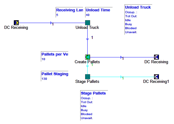
First, go inside the Receivals subsystem to add more detail there, like in this example.
The object named “Create Pallets” is called a Splitter, and is available from the Object Palette.
In Object View (Ctrl+O), add the splitter, and add a multi-server.
Name them as above.
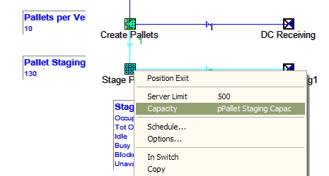
Set the capacity of Stage Pallets to a Portal Attribute (“Pallet Staging Capac” in this example).
Ensure the Stage Pallets Server limit is greater than what you think the maximum capacity might be.
Add an alternate portal exit, by clicking on the original portal exit and selecting "Add Alternate Exit".


